Synchronous motor vs Induction motor:
In AC motor there are two types:
1. In construction wise:
Synchronous motor has stator wounded on winding for specific number of poles and a salient pole rotor which is energized by DC supplysimilar to that of synchronous motor but the rotor may be short circuited squirrel cage or changing slip ring
2. In Speed wise:
3. In working principle wise:
Synchronous motor principle is magnetic locking, where as Induction motor principle is Relative Magnetic Field (RMF) as it is based on Lenz law
4. In power factor wise:
Synchronous motor has the ability to operate in leading, lagging and unity where as Induction motor always runs in lagging
5. In maintenance wise:
Induction motor will have brushes and slip rings where as synchronous motor is free from all those cost
6. In efficiency wise:
Synchronous motor will have high efficiency compared to Induction motor because of synchronous speed
7. In cost wise:
Synchronous motor cost is higher than Induction motor cost
What is synchronous motor:
Synchronous motor is an AC motor in which at steady state rotation of shaft is synchronized with the frequency of the supply current.
It's rotating period is integral number of AC cycles
Synchronous motor construction:
As like other motor synchronous motor also has stator and rotor
Stator :Synchronous motor construction is similar to the other motor where the stator is wounded on winding s for a specific number of poles. Stator is laminated with silicon to reduce hysteresis and Eddy current losses
Rotor: Rotor is salient type. The rotor windings are connected to DC power supply through slip rings
Always thenumber of
Working Principle:
The 3 phase supply is given to the stator as soon as the supply is given stator starts to rotate at Synchronous speed to produce a rotating magnetic field in the clockwise direction. When the DC supply is given to rotor it gets magnetized and produce rotating magnetic field.
Now the north poles of stator starts attracting north poles of rotor and the south poles of stator starts attracting south poles of rotor. As like poles repels each other the torque starts to rotate in anticlockwise direction. At this condition the motor won't run.
To avoid such condition the rotor is also rotated upto synchronous speed using DC supply. So the stator can skip the same pole in time difference. Now the two opposite fields will attract each other. Both stator and rotor rotates at same speed this is called as magnetic locking.
Do synchronous motor operate as synchronous generator:
The synchronous motor can operate as synchronous generator as they are same in construction by giving mechanical input. when we give mechanical input using turbine then rotor can rotate and as per principle of electromagnetic induction we will get voltage across stator winding having frequency dependent on speed of rotor
In AC motor there are two types:
- Synchronous motor
- Asynchronous motor or Induction motor
1. In construction wise:
Synchronous motor has stator wounded on winding for specific number of poles and a salient pole rotor which is energized by DC supplysimilar to that of synchronous motor but the rotor may be short circuited squirrel cage or changing slip ring
2. In Speed wise:
As we know Synchronous motor always runs at Synchronous speed where as Induction motor runs at speed less than\n synchronous speed
Synchronous speed: N =NsInduction motor speed: N<Ns
3. In working principle wise:
Synchronous motor principle is magnetic locking, where as Induction motor principle is Relative Magnetic Field (RMF) as it is based on Lenz law
4. In power factor wise:
Synchronous motor has the ability to operate in leading, lagging and unity where as Induction motor always runs in lagging
5. In maintenance wise:
Induction motor will have brushes and slip rings where as synchronous motor is free from all those cost
6. In efficiency wise:
Synchronous motor will have high efficiency compared to Induction motor because of synchronous speed
7. In cost wise:
Synchronous motor cost is higher than Induction motor cost
What is synchronous motor:
Synchronous motor is an AC motor in which at steady state rotation of shaft is synchronized with the frequency of the supply current.
It's rotating period is integral number of AC cycles
Synchronous motor construction:
As like other motor synchronous motor also has stator and rotor
Stator :Synchronous motor construction is similar to the other motor where the stator is wounded on winding s for a specific number of poles. Stator is laminated with silicon to reduce hysteresis and Eddy current losses
Rotor: Rotor is salient type. The rotor windings are connected to DC power supply through slip rings
Always thenumber of
poles of stator = poles of rotor
 |
| Synchronous motor construction |
Working Principle:
The 3 phase supply is given to the stator as soon as the supply is given stator starts to rotate at Synchronous speed to produce a rotating magnetic field in the clockwise direction. When the DC supply is given to rotor it gets magnetized and produce rotating magnetic field.
Now the north poles of stator starts attracting north poles of rotor and the south poles of stator starts attracting south poles of rotor. As like poles repels each other the torque starts to rotate in anticlockwise direction. At this condition the motor won't run.
To avoid such condition the rotor is also rotated upto synchronous speed using DC supply. So the stator can skip the same pole in time difference. Now the two opposite fields will attract each other. Both stator and rotor rotates at same speed this is called as magnetic locking.
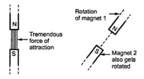 |
| Magnetic locking |
Do synchronous motor operate as synchronous generator:
The synchronous motor can operate as synchronous generator as they are same in construction by giving mechanical input. when we give mechanical input using turbine then rotor can rotate and as per principle of electromagnetic induction we will get voltage across stator winding having frequency dependent on speed of rotor
Comments
Post a Comment